Page 1 of 1
new brake upgrade bracket
Posted: Tue Aug 05, 2008 3:09 am
by juice_2
hi all have been looking at your brake upgrade using the nsx rotors and wilwood calipers, looks good only i have redesigned the bracket which in affect loses about 2.2kg according to the cad drawings calculations and it will also mount the caliper in roughly the same position as the origional caliper. we did a 3d cad drawing of your bracket and did a 1/1 scale print out of it and it didnt totally fit on an a4 piece of paper!!!!!!!!! thats alot of weight which in turn defeats the purpose of such a light caliper. so if anyones interested in seeing the finished product i'll post some pics.
Posted: Tue Aug 05, 2008 7:29 am
by Starion VR4
Am interested, could U PM me details so I caould have a look & see about getting some lazer cut... :beer
Posted: Tue Aug 05, 2008 9:25 am
by WidebodyWoody
agreed, post away
Posted: Tue Aug 05, 2008 9:28 am
by JJH
I'd be interested in seeing a side by side comparison of the two brackets.
Any impact on the road-worthiness of the lighter bracket & finally, could your bracket be modified to accept other calipers? Like nissan, rx7.
I don't have the capability to produce any of these brackets myself, so how much to have some made up?
:beer
Posted: Tue Aug 05, 2008 10:57 am
by juice_2
we are probably about a week or to away from finalising the cad drawings and templates then i am getting a set of brackets water cut as soon as thats done i'll post pics and pm anyone interested in them, as for the legality for roadworthyness unless you spend 1-2k on brake reaction and stress testing by a certified road traffic engineer they are illegal. but in saying that i am confident they will look standard, and being made from 10mm plate with less area than the ones posted by merlin and cookie the weight difference will be huge. but bare in mind you have to cut the strut as the origional mounts have to be removed. it will make more sence when you see it. any way when its happening i'll post a bucket load of pics. as for fitting an rx7 caliper it could but i would need a caliper to work out the pad mounting heights and offsets for caliper bolt hole location because i'm not sure if the wilwood and rx7 calipers are offset the same.
Posted: Sat Aug 30, 2008 10:23 pm
by shift1313
the drawing that is posted has the wrong location for the caliper so you know. im not sure what their current revision is but i used the caliper mounting guide from wilwood and it give you location based on rotor size. the rotor size(11.1") wasnt on their list so you need to do a little math to get the numbers. mine came out an extra .15" away which puts my pad right at the edge of the rotor. if you wanted a little room you could do less.
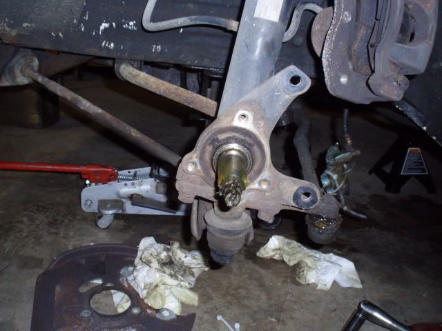
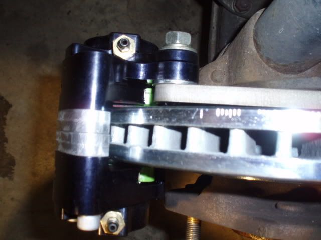
The reason for the lighter calipers wasnt weight reduction. Its so you can run a larger(wider) rotor and run larger surface area pads with more available options. my steel brackets .375" wide arent heavy at all and i like knowing i have a little piece of mind when it comes to this. I played around with mounting the wilwood calipers in the stock location with a small adapter piece but they dont physically fit there unless you modify the strut and remove the stock cast mounting ears. I also looked into finding larger od stock width rotors and i couldnt find any. I wanted to reuse the stock caliper(26mm) but there just arent many rotors out there that will work.
Keep in mind when you run stress analysis on your part the direction of the load in relation to the bolt holes(tangent to your rotor). The green stuff pads im using have a nominal coefficient of friction of 0.55. Depending on if your planning to use 4pot or 6pot the dimensions are available for surface area.
I think when i was doing my calculations(dont have them in front of me) i used 700lbs of force (a little over 3000 N) at each bolt.
id be interested to see what you come up with.
Posted: Sat Aug 30, 2008 10:39 pm
by shift1313
i would also like to mention one thing.
Using the original mounts is a great benefit because they were designed to take the forces put on them. They are out a good bit from the center of rotation so they have a decent advantage on the forces. The 3 bolts in the center were only ever designed to hold the dust shield. They are 8mm. the stock caliper bolts are 12mm, the new wilwoods are 10mm. Personally i wouldnt trust all those forces to 3 8mm bolts located that close to the center of rotation axis. I was so concerned with them in addition to the stock caliper bolts that i used grade 12.9 for those smaller 8mm bolts for shear strength properties.
i believe you are trying to make something like this

ps my steel plates weight 2.75lbs(1.25kg)
and here was an exerp from my orig analysis
"what i can tell you is the 3/8 plates weight 2.75lbs and the 1/2" plates weight 3.66lbs. Both brackets are constrained at the two orig caliper bracket holes and the 3 smaller holes around the hub. Both new caliper bolt holes were loaded with 707.1lbf in the tangential direction of the rotor. I did a bunch of calculations to try and get an accurate force but without knowing the coeff of frictioin between the pads and the rotors it was just a guessing game.
the max equivalent stress(you can see the point labeled max in the pics) on the 3/8" plate was 8000psi. the max on the 1/2" plate was actually a little more at 8112psi. This is because there was less deformation so the force was translated to the smaller bolt, which isnt mean to carry that kind of load!. Because of this point the factor of safety is actually higher on the 3/8 plate at 3.75, 1/2 plate is 3.7.
max deformation of the 3/8 plate is .00116" and its at the bottom caliper bolt hole. Max on the 1/2" plate was .000882" at the same point."
Posted: Sun Aug 31, 2008 2:16 pm
by juice_2
that is similar to what im doing but, i wont be using 8mm bolts they will be taken out to 10mm and the back of the bracket is getting cnc machined to fit over the raised section that the dust plate bolts to so in affect any inertia from the bracket is carried through the strut leg area and not solely on the bolts. the plate i'm using will start at 20mm and be machined to 10mm and be offset with machined gussets through the angle. computer simulated load tests show that the area that takes majority of the load force is the strut not the bolts. the comparison of load from the bracket bolts to the caliper bolts has a minimal if not no loading difference at all. so when load testing and everything else is done with this data i should be able to get them approved for road use. then it would be a case of modifying mounting positions to suit whatever caliper is required. ive gone a bit further into it than just a case of slapping a bit of plate to the strut, i want it to look like a factory caliper bracket just like the bolt on brackets they used on the first tx geminis. so when the testing stage is over and the brackets are machined i'll post some pics. but testing is taking longer as my mate who has access to the testing equipment has been too busy with work to finalise everything so i can get the machining done. i'll keep you posted.............
Posted: Sun Aug 31, 2008 9:30 pm
by shift1313
are you using steel for your material?
maybe some time today i will redo my force calculations to get an exact force to take my car down to 0mph.
i could be wrong but i think you will be very hard pressed to get the back of your bracket to match up to the stock unit because just below the machined surface is a large filled that goes down into the strut body. also taking those small holes out to 10mm wont leave you much meat around them which would be the main load points.
the fea pictures i posted may be deceiving just looking at them. The difference were in thickness, material and the number of bolts used. when you look at the drawing for instance that i only used the orig. caliper bolts, the equivalent stress is higher at the top bolt but only because of the leverage between the two points, but the larger 12mm bolt can handle that. I also think where you machine it down to 10mm you need to be very careful about the type of edge you leave because that will be a huge area for stress risers.
also from the mounting face where the 3 bolts go i only mounted the caliper another 1.8mm back from that face so you will have to take of8.2mm off of your bracket at the caliper location.
i realize how this might be coming off but i dont want you to think that I am discouraging you in any way. I just want to give you all the info I have that may be useful before you make a bracket while its still in the design phase.
ill see if i can get some time together today for that more accurate braking force calculation assuming the .55 friction of the ebc greens.
Posted: Tue Sep 02, 2008 1:10 pm
by shift1313
hey juice. ive done a bunch of calculations but im not even close to having even a general model of all the forces going one(excluding suspensions, weight transfer, air drag etc) since im in the US all my calculations are in ft, lbs etc so you will have to convert some of these over if you want to use them. Here are some forces that i have come up with(still havent checked everything over)
Stock US spec brake pedal has a 4:1 pedal ratio meaning if you input 300lbs of force on the pedal(leaving out components of force/angle) you will get 1200lbs going to the brake rod. The stock US cars have 15/16" diameter master cylinders. F/A = 1729psi in the brake lines. Transfer this over to the wilwood 4pots and you have 16,630 lbs of clamping force per front caliper and 6864 lbs of clamping force per rear caliper(2.25" diameter single pistons) . i did find somewhere that stated a single floating caliper would need to multiply the clamping force x2 giving you 13728lbs of clamping force per rear caliper. Im going to look into this more ofcourse.
Ill break down the rest into sections:
Frictional force of the pads:
assuming .55 coeff of friction
Ffric front = 9150lbs
Ffric rear = 7550lbs
Torque on the Rotors
Tr front(11.1") = 40300 inch-lb
Tr rear(10.1" but didnt measure) = 29445 inch-lb
Friction Force on tires
Ftirefront = 3042lb
Ftirerear = 2220lb
The total braking force between the vehicle and the ground = 10520 lbs
all this data will be needed along with weight transfer numbers for me to figure out the best rear braking setup. moving along
Deceleration with these figures
This is theoretical but i got 120 ft/sec^2. This is an extremely high number i think and it assumes a lot of things that just arent true about efficiency.
I also did an integral with respect to time on what Average accel(decel) would be needed to go from 100mph to 0 in 10seconds and got -14.66 ft/sec^2. keep in mind this is the average over that time and distance. Im going to go back and figure out some other instant accels for these figures(when i have time).
i also calculated the stopping distance from 100mph using the figures above and got a distance of 90ft . that is with this front brake upgrade and stock rear.
i cant stress enough that these numbers are theoretical and make a bunch of assumptions. I am going through these calculations to figure out the "worst case" for transmission of braking forces to this bracket for safety reasons. This is basically the things a safety engineer would go through to figure if this was okay as well as durability tests etc with actual parts.
Within a week or so i hope to have a somewhat accurate over assumption of braking forces and within a month or so a more accurate understanding of the entire braking effect of the car.
just as a comparisson an acura nsx goes from 60mph-0 in about the same distance i figured for 100mph - 0. These numbers do not take into account frictional forces between the tires and also heat, air resistance and suspension which will absorb some of the braking forces. hopefully this is clear and somewhat usable for your design.
Posted: Tue Sep 02, 2008 8:21 pm
by juice_2
ill be using a 1 inch master cylinder, the plate is high tensile moly with high tensile 10x1.25 cap bolts, these will work as you need 1mm of thread pocket depth per 1mm of bolt diameter and from memory the area i am mounting it to is 13mm deep. also there is 6-7mm from wall width from edge of bolt hole to the edge of the strut which is sufficient, i have done brake mods on rally cars with less quality materials and smaller tolerances and have never had one fail. also you will need to take into account engine braking on decell because in the real world under race conditions unless you've totally got it wrong engine breaking is a major factor in pulling up a vehicle. no matter how good the brakes you will lock and slide the vehicle without the engine braking factored in (no abs). the inertia of the vehicle travelling at 100mph will over ride the grip level of the tyres (subject to what tyre is used) also. so in theory you will lock and slide under extreme braking before you break the mounting bolts especially when with my bracket design as it will be recessed to distribute the load to the strut via the recess machined into it to fit over the backing plate mount area. but all that being said until its put into operation you never know what will happen. keep up the good work man good to someone who is thorough in there designs.
Posted: Tue Sep 02, 2008 8:30 pm
by shift1313
i definitely understand about engine braking but i wanted to come up with force numbers assuming the tire never slipped having all the available friction it needed(thats why the theoretical stopping distance number i had was very unrealistic compared to average deceleration). While i do have some math behind me, to solve this problem dynamically is above my level and would take me forever:)
i cant wait to see what you come up with for this
Posted: Tue Sep 02, 2008 10:37 pm
by juice_2
my best mate who is an absolute rev head is a university qualified engineer and the math he throws out at me makes me feel like an absolute idiot. he's doing all the measurement calculations and loading calculations. when i looked initially at the design here i gave him the dimensions to rectify the mounting position of the caliper he drew it up in 3d on his cad program and then came up with the basic idea of the new bracket, (he designs and manufactures mechanical seals and pumps for the mining industry worth shitloads and the tolerances are calculated in some cases in lightbands so he knows his stuff) his initial design started as a straight bolt on bracket with no recess at the rear of the bracket, but the first thing whe discovered was the inertia of the bracket on the mounting bolts would cause failure so by adding the recess at the rear it reduced the inertia loading by upto 86% caluculated at a speed of 120mph, as for pedal forces etc. i dont know exactly what calculations he worked out, thats when the math turned my brain to sludge.....but being the perfectionist he is it will work just have to make sure everything is right before we start manufacturing. so i'll keep you all posted.