Als POS


Got myself a donor engine to hopefully swap some bits into.
RWD block wouldn't turn when I got it, so I started stripping it down to find out why. I think I found the issue!
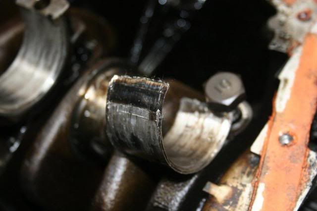
#1 rod
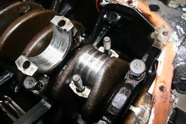
#1 bearing
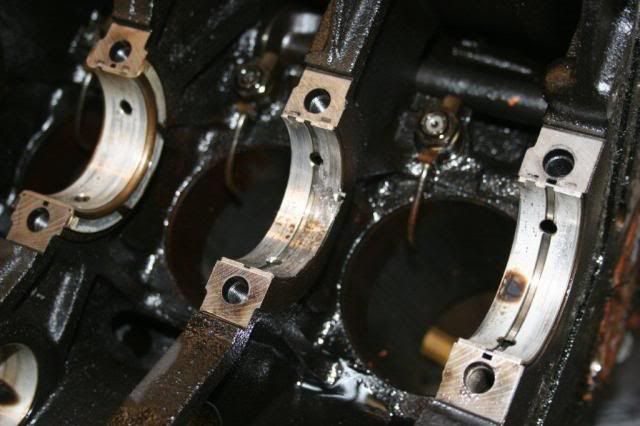
Crank bearings not too happy either

Measured the main bearing bolt centres to ensure the fwd crank will fit in rwd block. Also measured if the snout lengths are the same....
FWD
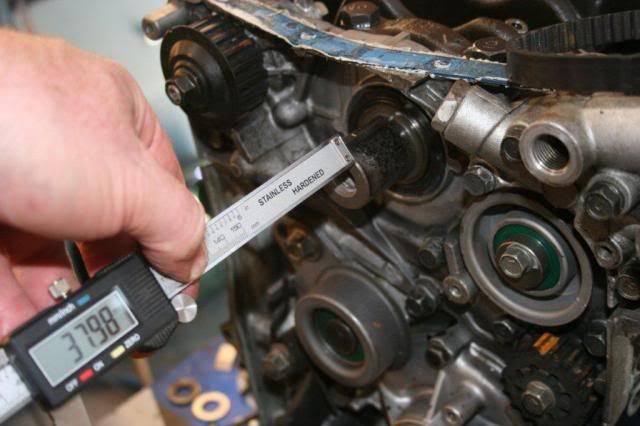
RWD
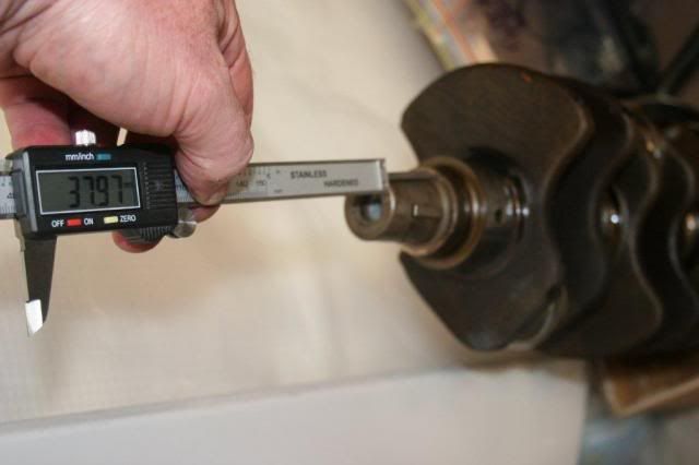
SAME!
Differences in flywheels for info.
FWD
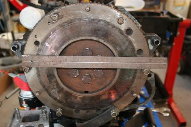
RWD
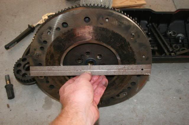
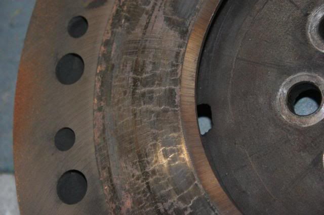
Not sure if the flywheel from RWD engine is any good, going by the amount of clutch dust and spots on the flywheel....and the cracks. Can they be machined out?
Stay tuned.
RWD block wouldn't turn when I got it, so I started stripping it down to find out why. I think I found the issue!
#1 rod
#1 bearing
Crank bearings not too happy either
Measured the main bearing bolt centres to ensure the fwd crank will fit in rwd block. Also measured if the snout lengths are the same....
FWD
RWD
SAME!
Differences in flywheels for info.
FWD
RWD
Not sure if the flywheel from RWD engine is any good, going by the amount of clutch dust and spots on the flywheel....and the cracks. Can they be machined out?
Stay tuned.
-
Komeuppance
- Enthusiast
- Posts: 607
- Joined: Fri Nov 16, 2007 3:50 pm
- Location: Oregon, USA
- Contact:

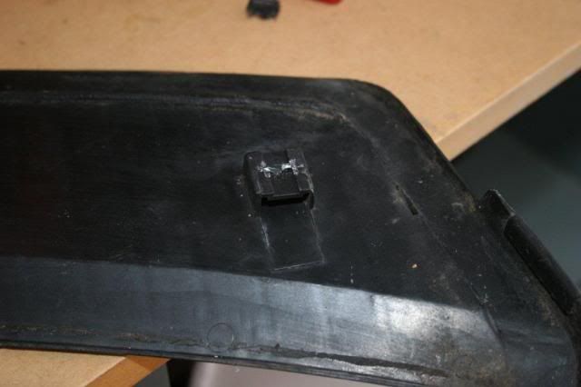
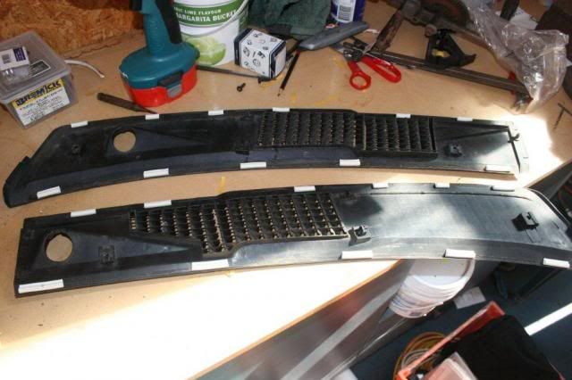
Latest fix. Windscreen garnish that has clips made from notavalablium. So the next best option is to whack a couple of screws in them. I put two screws in each piece of the garnish (the two outer most mounts, not the two centre mounts)
Others have done this, just figured I'd show you how I did it.
I found some grommets on ebay which are a perfect fit into the rectangle in the cowl.
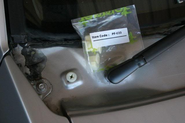
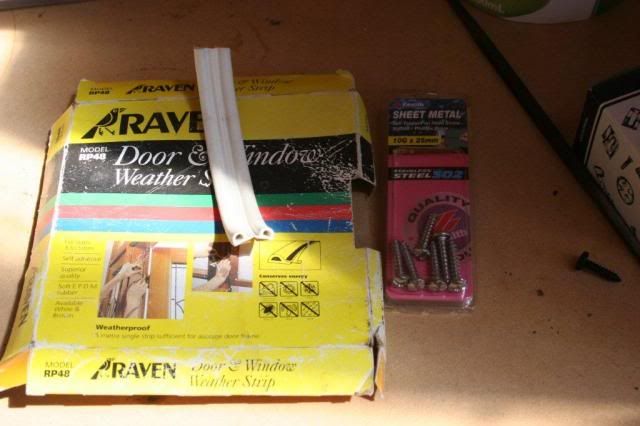
10G x 25mm long stainless screws and some sealing tape (for doors)
Clips are long destroyed and gone.
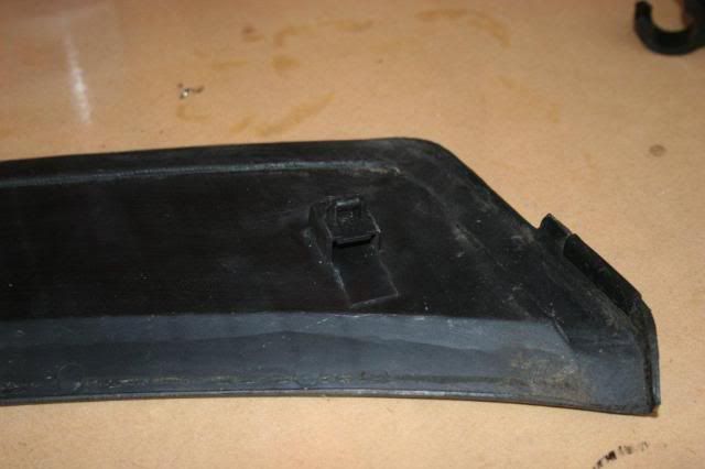
So....chop!
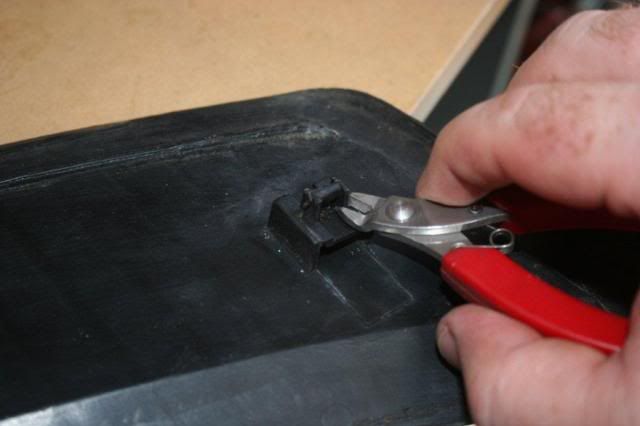
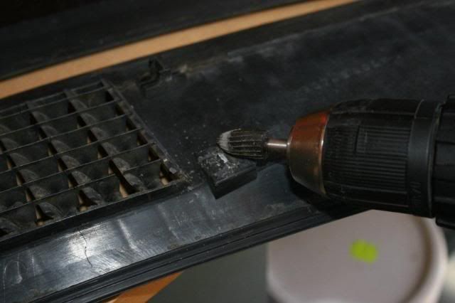
Eeek...too late to turn back
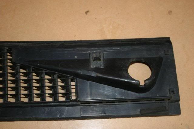
Smooth the bits of plastic off, dig a small furrow in the middle of the mount.
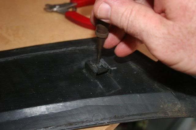
Centre punch in the centre
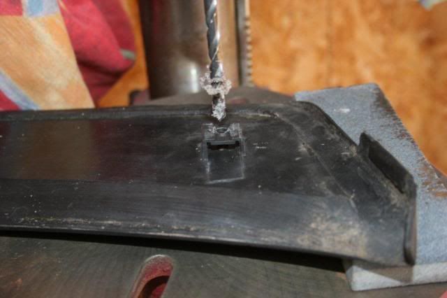
Now using 3mm drill....slowly drill from the mount side through the two layers. Be extra slow and careful. Ensure the drill is square to the mounting face
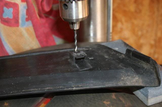
Then using 5.5mm or 6mm drill, drill all the way through
Done....repeat for the other outside mount points.
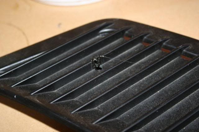
In a couple of places, the hole will appear right on one of the fins. So...very carefully, chop the fin to fit the head of the screw.
I used a soldering iron to melt most of it out, stanley knife and scalpel to finish chopping the plastic, then p180 sandpaper.
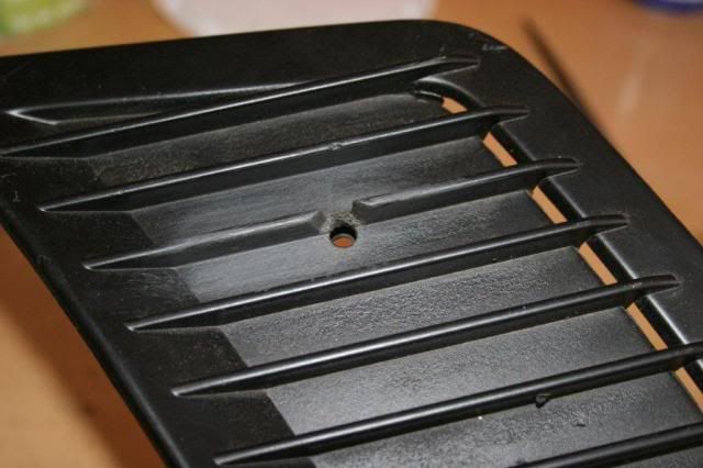
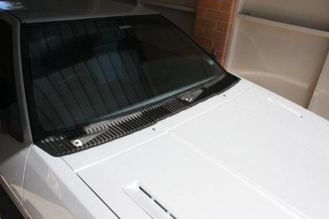
After ages, it will look like this. I coated with paint after.
Once all the holes were done and cleaned up, I test fitted it all. I found there are rubber extrusions missing from around the plastics, so using the door seal I placed a few bits in to space the plastic from the windscreen and cowl. I'll go back later and put something black in there, for now this will do.
Then refit the plastic trims and just nip the screws up very gently to just stop movement, no doubt if you do the screws up too tight you will crack the plastic.
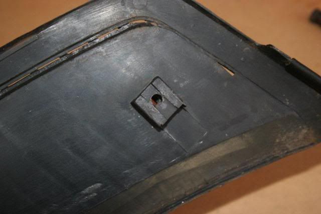
Also, one small thing, the screw hole under the passenger wiper is on an angle. I ground down a small plastic washer into a wedge so the screw top is flush when you screw it down.
This is the underside of that hole/mount.
Others have done this, just figured I'd show you how I did it.
I found some grommets on ebay which are a perfect fit into the rectangle in the cowl.
10G x 25mm long stainless screws and some sealing tape (for doors)
Clips are long destroyed and gone.
So....chop!
Eeek...too late to turn back
Smooth the bits of plastic off, dig a small furrow in the middle of the mount.
Centre punch in the centre
Now using 3mm drill....slowly drill from the mount side through the two layers. Be extra slow and careful. Ensure the drill is square to the mounting face
Then using 5.5mm or 6mm drill, drill all the way through
Done....repeat for the other outside mount points.
In a couple of places, the hole will appear right on one of the fins. So...very carefully, chop the fin to fit the head of the screw.
I used a soldering iron to melt most of it out, stanley knife and scalpel to finish chopping the plastic, then p180 sandpaper.
After ages, it will look like this. I coated with paint after.
Once all the holes were done and cleaned up, I test fitted it all. I found there are rubber extrusions missing from around the plastics, so using the door seal I placed a few bits in to space the plastic from the windscreen and cowl. I'll go back later and put something black in there, for now this will do.
Then refit the plastic trims and just nip the screws up very gently to just stop movement, no doubt if you do the screws up too tight you will crack the plastic.
Also, one small thing, the screw hole under the passenger wiper is on an angle. I ground down a small plastic washer into a wedge so the screw top is flush when you screw it down.
This is the underside of that hole/mount.
-
WidebodyWoody
- Woodwide
- Posts: 3133
- Joined: Thu Jan 08, 2004 6:24 pm
- Location: Gold Coast
- Contact:
Who is online
Users browsing this forum: No registered users and 1 guest